This video introduces the early low-cost DIY route of QuadRank Timer: ESP32/ESP8266 is responsible for running timing and interface services, RX5808 with SPI receives image transmission and outputs RSSI, and the mobile phone application is used to select channels, calibrate and set detection sensitivity. The tutorial covers materials, wiring, firmware flashing, power supply and basic calibration, but was recorded in 2021. The download address, pins, application price and platform support should be subject to the current FPVSIM Timer document.
Why a personal timer helps, and how the system works
Reliable lap times let pilots compare which laps are faster, check whether a change of line actually helps, and distinguish an occasional fast lap from repeatable consistency. After trying a short-range Bluetooth solution, the video author builds a personal timer using a Wi-Fi development board and an FPV video receiver module. The connection held over a test distance of about 20 meters, but that result depended on the particular site and antennas and should not be treated as a guaranteed range.
Two parts work together: the RX5808 listens on the selected video-transmitter channel and provides RSSI signal strength. The ESP development board reads the signal, runs interface services, and passes the status to the phone app. RSSI rises as the aircraft approaches the timing gate and falls as it departs. The app uses calibration results and sensitivity thresholds to identify a valid crossing. Reliable timing therefore depends on RF placement, thresholds, and the software connection, not merely on correctly soldered hardware.
Do not choose parts or wiring solely from old footage
The recorded version supports ESP32 and ESP8266. The author notes that ESP32 has a higher clock speed and two cores, theoretically providing more processing capacity. Choose an RX5808 receiver with SPI; otherwise additional board modification is required. The video also uses three 1 kΩ resistors and one 100 kΩ resistor. Before buying, check the current bill of materials and confirm that the development board, RX5808 revision, and resistor network remain compatible with current firmware.
The demonstrated SPI control lines are CH1, CH2, and CH3. On the ESP32 board used, RSSI connects to GPIO34 and into the corresponding network through a 100 kΩ resistor. However, silkscreen labels and pin mappings can differ between board models. Do not solder solely from a transcript or screenshot. Compare every wire with the current wiring diagram, use a multimeter to check for shorts and correct supply polarity, and only then connect the RX5808 and USB power.
Firmware must match the development-board target
After completing the hardware, the video uses the Windows flashing tool available at the time to select a serial port and write firmware. ESP32 requires the ESP32 target; ESP8266 requires its corresponding target. A wrong image, wrong serial port, or interruption under unstable power can prevent the device from booting. Before flashing, save the file-checksum information, confirm that the USB cable supports data, and watch for abnormal heating at first power-on.
The video’s 1.0 firmware, download page, Android app, iOS release status, and price of 9.9 yuan are historical information. Obtain current firmware, flashing tools, and app links from fpvsim.com/timer or current official documentation. Do not infer from an old video’s addresses that compatibility or pricing remains unchanged.
Choose the channel, calibrate, and test the detection boundaries
After connecting the phone to the timer, first select the video-transmitter channel actually used by the aircraft, then calibrate at the real timing-gate location. Calibration observes the signal peak as the aircraft approaches. Sensitivity determines the signal levels at which the system considers the aircraft to enter and leave the detection region. A threshold that is too high can miss laps; one that is too low can trigger outside the gate. Make repeated passes with the actual power, antennas, and flight path, rather than merely bringing a VTX close once on a desk.
If connection range is insufficient, the video mentions fitting an external antenna according to the relevant development-board instructions. This changes RF coverage and may also enlarge the false-trigger region. Recalibrate after modification, then test gate crossings, flights beside the gate, circling outside it, and fast consecutive laps. Before regular use, also check that spoken lap times, app records, and an independent reference agree.
Operation steps
- Prepare hardware from the current bill of materials
Choose an ESP32 / ESP8266 supported by current firmware, an RX5808 with SPI, and the specified resistors. Do not order solely from the 2021 purchase links.
- Verify RX5808 and RSSI wiring
Check CH1 / CH2 / CH3, RSSI, power, and ground wire by wire. The board in the video uses GPIO34, but follow the current diagram for the board you actually have.
- Check soldering and power
Before powering on, use a multimeter to check for shorts, polarity, and the resistor network. At first power-on, immediately watch for abnormal heating in the RX5808, development board, or regulator section.
- Flash firmware matching the development board
Select the correct serial port and ESP32 / ESP8266 target. Keep a stable connection with a data-capable USB cable, then confirm that the device boots normally.
- Use the current phone app or web entry point
Obtain the app or web entry point from current official documentation. Android / iOS availability, pricing, and download addresses in the video describe the recording period.
- Calibrate each channel and test at the venue
Select the actual VTX channel, make repeated passes at the real start/finish point, adjust sensitivity, and check for missed laps, double counting, and triggers outside the gate.
FAQ
Can ESP32 and ESP8266 firmware be used interchangeably?
No. Each board requires its own target. Pin assignments, performance, and firmware images differ; also check the current support list before flashing.
Can any RX5808 module be used directly?
The video requires the SPI version. A board without SPI may need additional hardware modification. Pin assignments can also differ between revisions, so follow current materials and wiring documentation.
Does GPIO34 in the video apply to every ESP32 board?
No. That connection applies to the board model used in the video. Development-board variants may have different available ADC pins and silkscreen labels. Verify the specific model.
Does higher sensitivity always mean fewer missed laps?
Not necessarily. Easier triggering can also cause counts outside the gate or duplicate laps. Test both missed laps and false triggers at the real venue before deciding on thresholds.
Full timeline transcript
Transcripts are arranged according to video time, making it easy to quickly locate the explanation content. Transcript language: Simplified Chinese.
Hello everyone, I am QuadRank. Today I want to share a recent project: a personal racing timer. A timer is very important when I practice racing. It tells you which laps are fast or slow, helps you work out why, and lets you keep improving your lines. I looked at the personal racing timers available on the market—
—and first bought this one. Everything about it was fine except that I could not actually use it. It connects by Bluetooth, and the range was very short: beyond two or three meters, it would no longer connect. The supplied app was also extremely difficult to use. For me, it was effectively a brick after purchase; I never got it properly working.
There is another one, transcribed here as “Left RF” from “Emergency Rc.” I do not know whether any of you have used it. I heard it was better, but range was still a problem: at around 10 meters it would no longer connect. Its app was also very dated. I wondered whether I could use my own professional skills—I work in software—to build a racing timer. I happened to have an ESP 8266 board at home.
I then bought an RX5808 receiver, which led to today’s project. I have used it for over a month from the prototype onward, and it has worked very well, so I refined it further to share with everyone. To see it operating, watch my previous video, which shows a test in the park today.
The racing timer was about 20 meters away from me without disconnecting. Let us see how you can build one at home. First, the required materials—
—the code currently supports two development boards: ESP32 and ESP8266. ESP8266 is slower. ESP32 can run at 240MHz and has two cores, so theoretically ESP32 should be faster. These boards are sold on Taobao and are very inexpensive: one costs 12.8 yuan.
Those outside China should also be able to buy one inexpensively. There is also a light, and this RX5808 board, which receives the video-transmitter signal. We use RSSI signal strength to determine whether the aircraft is near a gate, enabling timing. Be sure to buy the version with SPI; without SPI, you have to modify it manually, which is very troublesome.
We also need three 1000-ohm resistors and one 100-kilohm resistor for the wiring below. They are very cheap. Here is the system overview: the ESP32 acts like a small computer, and the RX5808 receives the video-transmitter signal. The ESP32 uses the signal strength on the RSSI pin—
—the ESP32 also runs an API Server. There is a QuadRank Android app, and iOS is supported too, but it has not yet been published to the iOS App Store. For now, Android is what you can use. Of course, in the future, if—
—many people use iOS, please leave a comment below and I will publish it to the iOS App Store as soon as possible. The app connects to ESP32, allowing you to calibrate, set the video-transmitter channel, and read each lap time. That is the system overview. Now let us look at wiring, which is very simple, compared with—
—one of my small aircraft, because there are only 6 wires in total. Three carry SPI: CH1, CH2, and CH3 connect to ESP32 or ESP8266. The wires are shown here; connect them to the corresponding pins.
When connecting an ESP32, make sure RSSI goes to GPIO34. There must also be a 100,000-ohm resistor between RSSI and ground; do not forget it. Once the wires are connected, the hardware is complete. Here is a timer I made yesterday. These are the three 1000-ohm resistors, and this is the 100,000-ohm resistor. I connected the wires directly—
[Speech cannot be reliably recognized here]
[Speech cannot be reliably recognized here]
[Speech cannot be reliably recognized here]
—find a USB cable and plug it into the USB port to supply power, which also powers the receiver. After completing the timer hardware, install the phone app. The installation link is here. The app is currently paid, priced at 9.9; I hope you will support QuadRank. Thank you. Once you have downloaded it—
—there are two screens: the normal timing screen and the settings screen. Settings are simple. One selects the video-transmitter channel with a tap. Another is calibration, which finds where the signal is strongest. Another sets detection sensitivity. What is sensitivity for? It determines when the aircraft—
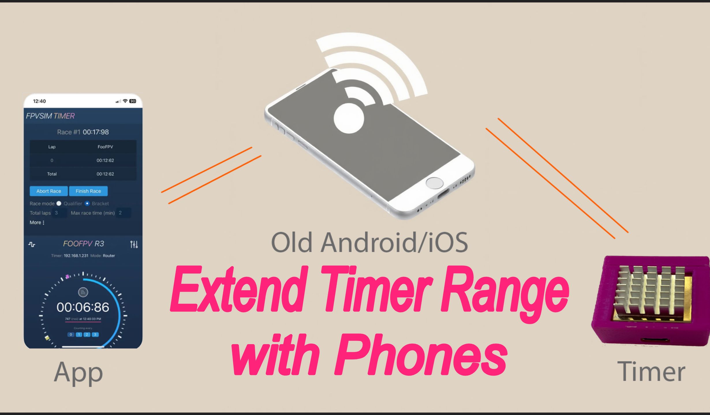
—is counted as having entered my detection region and when it has left, so timing is accurate. With these two components, the timer is complete. If the range is insufficient in testing, you can fit an external antenna. I have also linked instructions here for fitting one to ESP8266 and ESP32 boards.
You can follow these pictures to modify the external antenna. After fitting it, a distance of twenty or thirty meters is no problem.